[pi] Headless pi connection with VNC on Mac system

Sometimes we have to access our pi with limited resources like lacking of monitor or keyboard. The Headless mode is useful to connect to your pi with another computer or your laptop without additional screen!
Now let’s get started to give it a try!

Setting Raspberry pi board

Connection to pi
connect to raspberry pi board with

ssh pi@rapberrypi.local

and input your password(Default password has been setted to raspberry)

Configue the VNC
Input

sudo raspi-config

Navigate to Advance Option
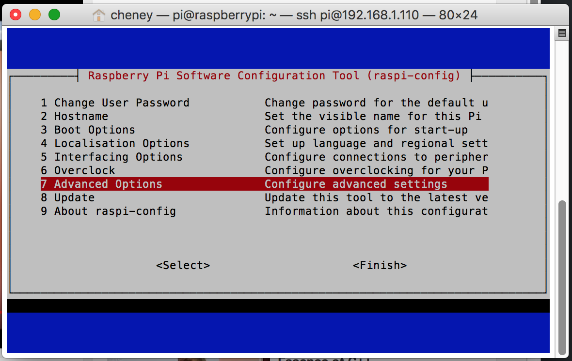
enter image description here

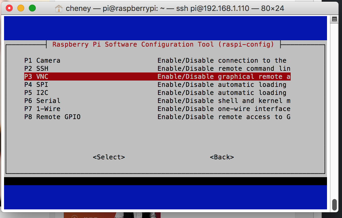
Select [P3 VNC] and click [OK]
enter image description here
After setting up of the VNC, reboot the pi

sudo reboot

On Mac

Downlaod VNC viewer from:
https://www.realvnc.com/en/download/viewer/
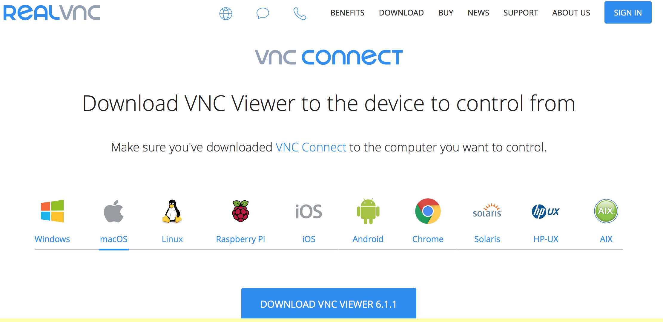
enter image description here

After installed the VNC viewer, Input the IP address of raspberry pi and click Continue.
enter image description here
Now we have successfully connect to our pi with VNC!
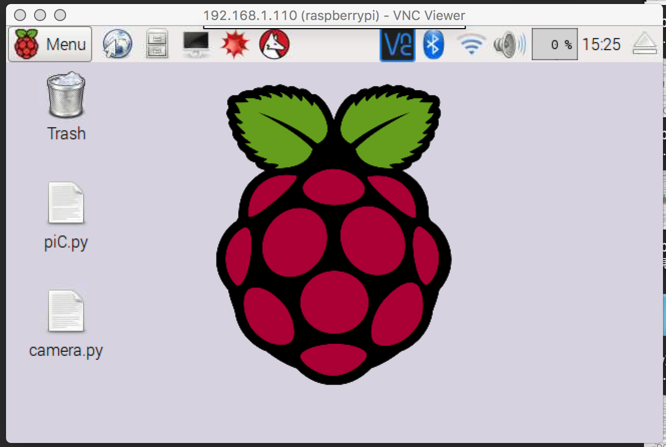
enter image description here

Improve the resolution

We have justed connected to the pi with VNC. However, the screen is quite small and the resolution wasn’t really good. How can we improve it?

Let SSH to our pi gain with

ssh pi@192.168.1.110

(192.168.1.110 is my pi’s address)
Now we need to modify the config.txt setting for better VNC viewer resolutions.

sudo nano /boot/config.txt

uncomment and change the HDMI settings

hdmi_group=5
hdmi_mode=85
hdmi_ignore_edid=0xa5000080

hdmi_mode=85 represents the resolution of HDMI mode will be setted into 1280x720.
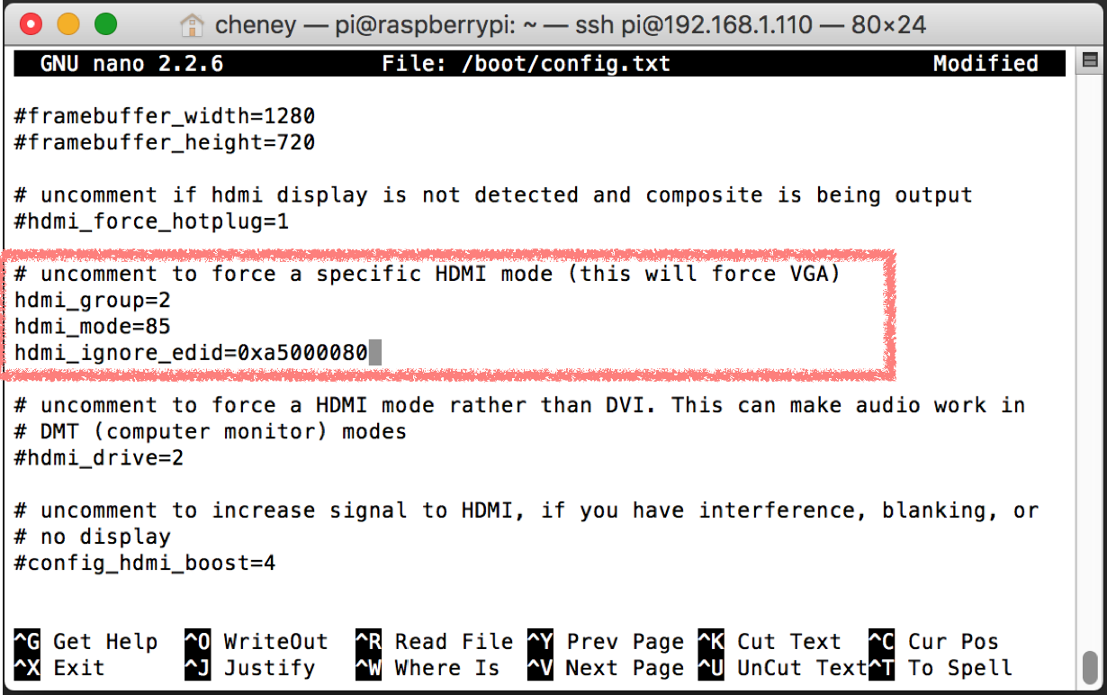
enter image description here
after the parameter setting, click [Ctrl+X] and click [Y] and [Enter] to modify the config.txt file.

After all the setting processs, we can now reboot the machine.

sudo reboot

Connect again with VNC Viewer

If everything goes well. The resolution of HDMI mode will be setted to 1280x720 like the screen shot showing below :-D
enter image description here

Happy piING~

Comments

Popular posts from this blog

Arduino CNC shield control Stepper motor with DRV8825

CNC shield is quite useful for stepper motor driving. Here, I demonstrated how to use simple arduino code to drive stepper motor with DRV8825. First, just simply mount CNC shield onto Arduino Uno. Make sure the direction of the shield was right, where both the USB port and power supply wire was on your left hand site. The blue wire is my power supply which can be connect to 12-36V of power source. Next step you can mount the DRV8825 chip onto the CNC shield. Make sure the DRV8825 chip goes like this direction. If you put the chip in the wrong direction, you will probably damage it. By adjusting the jumber underneath the DRV8825 chip, motors can be driven with different kind of microstepping mode. I put three number here so it means that I set it into 1/32 step driving mode. Which is the most precise  one of DRV8825. The motor can connect to the right site of the DRV8825. Plug in the usb to your computer and upload these coded which will generate...

Connect Arduino Wemos D1 ESP8266 to Internet/Wi-Fi Router

Connect ESP8266 to Wi-Fi Router Upload these code to your Arduino WeMos D1 ESP8266 W-Fi board. #include <ESP8266WiFi.h> //SSID of your network char ssid[] = " myRouter"; //SSID of your Wi-Fi router char pass[] = " myPassWord"; //Password of your Wi-Fi router void setup() {   Serial.begin(115200);   delay(10);   // Connect to Wi-Fi network   Serial.println();   Serial.println();   Serial.print("Connecting to...");   Serial.println(ssid);   WiFi.begin(ssid, pass);   while ( WiFi.status() != WL_CONNECTED) {     delay(500);     Serial.print(".");   }   Serial.println("");   Serial.println("Wi-Fi connected successfully"); } void loop ( ) {} Using ESP8266 to connect to Wi-Fi need to use the function of: WiFi.begin(ssid, pass); // connect to target Wi-Fi SSID is the name of the Wi-Fi you want to connect to.  while ( ...

Can D13 pin of Arduino Uno and nano be use as input pin?

D13 pin can be use as  digital output pin. D13 pin can be use as i nput pin  together with  external pull-up  and  pull-down resistor . It is not recommand to use the  D13 internal pull-up  resistor because instead of the regular 5V, the voltage will be hanging around 1.7V. Most of Arduino newbies have their first code to blink the LED with D13 pin as an output pin. This really give us big confident to know the code can be successfully executed on the microcontroller. However, due to the build-in D13 pin on different Arduino board has slightly different circuit design,  is there any limitation to use the D13 GPIO pin as input pin ? Let’s find out more! Experiment condition I investigate both the value of D13 digital input and LED light status with the following code with  Arduino Uno Rev3 . and  Arduino nano 3.0.  void setup() { pinMode(13, INPUT); Serial.begin(9600); } void loop() ...